1955 Ford Part 5: Control Arms, Coil Springs, & Front End
- Hot Rod Reverend
- Sep 8, 2017
- 10 min read
Updated: Dec 27, 2019
(Note: You are reading the progress from a project that began in August of 2014. This information was originally dated from December of 2014 and January of 2015.)
Control Arms, Coil Springs, & Front End
Back to work on the Ford! It was now time to fix a problem I had from years ago when I can remember installing a shock mount. Basically one of the nuts had dislodged itself from the shock mounting location on the lower control arm. I think this happened when I was like 18 or something. Anyhow, I did get the nut to tighten down by sticking a screwdriver between the coils and hold it down while I put the bolt through. That was a long time ago. When I disassembled the front end, I knew I wanted to make sure those nuts were secure and that I needed to weld the loose one back to the control arm. Mission accomplished, and I decided to tack the other one in as well just for good measure.


Well the Christmas and New Year's Holiday was good - we had an excellent time with our kids, and a lot of in laws and “out-laws” showed up. I had planned to spend some time in the shop since I would have a few more days off for Christmas but my plans were made in vain. I looked at my calendar and most recent documentation... it has been well over a month since I have accomplished anything out there! Anyhow, I decided to fire up the diesel "turbo" heater in the garage (you know the kind - it sounds like a jet aircraft taking off and when you run cheap fuel in it you gag over the fumes). I have owned the one I have for 5 years. I believe it is 210K BTU if you run the higher pressure. Over the past 5 years - no problems... until tonight. I hit the switch and the spark plug makes it usual noise, then the fan and fuel pump engage, but no FIRE... when I look inside the cavity--- there is raw fuel on the bottom and it eventually runs out and down the side of the tank. What gives?

I thought "Well, that's probably the fuel being sprayed that would not ignite so where else could it go?" I look at the display panel on the side of the unit and wouldn't you know it, the panel reads "E1". I get out the trusty manual and it looks like it could be a dirty photocell that needs to be cleaned off. No biggie. I take off the top cover of the tube and have a "look see". I was shocked at the condition of the two fuel hoses - no wonder the thing was leaking fuel. I took pictures of the hoses and posted them below. Dry rot central. I have never seen rubber hoses go so bad in only 5 years and with very limited use at that. I guess I should have inspected under the cover each year before firing it up just to check on things, but there never has been a problem with this thing and I keep it very clean. Word to the wise if you own one of these units - the manufacturer uses CHEAP hoses and get this... NO CLAMPS!!! on a fuel pump that runs 8 psi!!!. I looked through my bins and found two, new, fuel injection, automotive grade hoses to install. Much more rigid and probably overkill. Suffice to say, the unit fired right up when I put it all back together and we were ready for action.
After the garage warmed up a bit, I decided to drill the drain holes for the front cross member and take a look at the Internal Frame Coating product from Eastwood (is it a 14 oz load of snake oil or is it the real deal? - I have no idea). Anyway, the idea is that the long narrow hose attaches to the aerosol can and using the 3 hole tip on the end, the user can slide the hose into the frame and coat the interior walls of the frame as he pulls the hose back out while he is spraying. Let me tell you that if you have any notion to use this kind of product, be prepared for a mess! I believe it worked well. As you can see from the photos, I did enough heavy coats to have the product coming out the drain holes of the cross member. It was messy enough that I need to go back and repaint the satin black on parts of the frame, but that's no big deal. This cross member is going to outlast my lifetime that is for sure! I already have the upper and lower control arms painted so we are getting close to beginning reassembly. I need to get the car rolling again so that I can move it in and out of the shop for body work.


I cleaned up the mounting bolts and did some work to the front end by installing the upper and lower control arms. When you get to a stage like this, it makes you very happy that you took notes and bagged and tagged your hardware. For instance, I decided to bag and label those shims that are used to align the wheels on the upper control arms. I also did that for the lower control arms where the large shim washers are used for the front of the control arm where it attaches to the cross member (more on that later though).

The hardware was blasted where needed and threads cleaned with a wire wheel. I also used copious amounts of bearing grease on the large shoulder bolts and a good dose of anti-seize on the mounting bolts for the upper control arms. I started with the driver's side lower control arm first. After laying down some fresh cardboard to keep my arms from getting scratched by the floor, I put the driver's side into position. Immediately I noticed that it was not a tight fit, and that if I installed the arm there would be play back and forth as the arm's bushings would slide on the shoulder bolts. Thinking I would rather have some "springiness" in there and make it tight rather than letting it slide around, I chose the shim(s) I needed to take out play and even had to use a pry bar to wedge it back in (not a lot of prying but enough to bring 1/8" in to meet up the holes). So I slid both bolts into the holes but did not put them all the way through. I then got the holes of the arms to line up with the holes on the cross members. After that, the bolts went through with just a little tap and we were set to reinstall the cup washer, lock washer, and nut.


A word of advice on the shim--- grease the side that goes towards the cross member. It will stay put for you as you align the arms since they are very snug. I did take a photo of the bolt being placed in the front cross member and where the shim washer goes. Note that the straight edge goes towards to the top to fit up under the lip of the cross member itself. It would be a good idea to check the fitment of all of your bolts and hardware before starting the installation process anyway. The shoulder bolts have a whopping 1 1/8" head and the nuts are 15/16". I decided to NOT tighten these arms to spec on their torque, just leaving them a little loose until I install the spindle and ball joints. I am not so sure whether or not anything will bind up, but I thought it wise to wait.
The upper control arms attach to the frame mounts without much fanfare...especially if you kept your shims labeled. I am not sure how much this will help with the front end alignment because of new parts, etc. But I believe it will help things out until I get the car to the shop and they are able to put it on the alignment rack. Note the orientation of the upper control arm also - the mount for the upper ball joint goes towards the REAR of the car. You need a 3/4" socket and/or wrench to meet the head and nut size. I put each control arm up into position and then slide the bolts through. I attached the lock washers and nuts, leaving things loose, and then I placed the shims in their correct locations. After that, the arms were torqued to spec and allowed to rest.


The picture below has a little back story. As I located all of the shoulder bolts and hardware for the lower control arms, I could not find one of the cup washers. "What did I do with that thing?" I asked myself. "Surely I didn't throw it away!" I groaned as I rummaged around. I finally decided to check my junk pile. Wouldn't you know it but one of the bushings that had basically disintegrated and fell off in my hands during disassembly CARRIED THE CUP WASHER with it. Glad I didn't just chuck it all in the trash! I rescued it, shook my head, and the cleaned it up for re-installation.

The next photo below is of the extra shims. I did save all of the shims and bagged them for which side, etc, when I removed the lower control arms a few months ago. So, why didn't I need to reinstall them? I figure it had to do with this... installing new bushings meant that the overall distance from end to end on where the arms would mount up to the cross member holes CHANGED. There is no way I would be duplicating the same distance from the factory and I believe that is why the shims are there in the first place - to take out the play from front to rear so the arm itself does not slide. The only movement it should have is rotating on the shoulder bolts themselves.
Time to get those spindles cleaned up! They are soaking in the parts washer as I write this post. And... I have new front springs to install. I have not yet purchased the shocks for the front end. The springs are the Aerostar springs (CC850) that will lower things about 2 inches. I already have new upper and lower ball joints and hardware. Sometimes you have moments when you stand back and admire your work. Other times you stand back and look and you say to yourself... "There's a reason I don't make a livin' doing this kind of thing."
If you are a very observant individual and know your 55/56 Fords very well, you noticed that I left out the two "collars" that surround the front bushing on the lower control arm. I really do not know what overall purpose they serve, but I reckon since Ford installed them originally I should probably put them back. So... off with the arms and on with the collars and reinstall the bolts and nuts!
Here is a photo of what I am talking about...
I did get the upper and lower ball joints installed, but I did not have the bumpers for the upper joints. The irony is that the kit I received had 3 bolts, nuts, and washers per upper ball joint, and then 2 bolts, nuts, and washers for the lower ball joints. There are 3 holes for each joint. I have the lower bumpers.... guess I need to order the upper bumpers or is there a reason why they are no longer needed? I have a set of the Aerostar coil springs and new rubber to insulate them in the frame all ready to go. They are waiting their turn. I did get the spindles cleaned today and gave them their first coat of paint.
Moving along I re-installed both spindles and the new coil springs. My 11 year old son came in the garage and said, "Dad, it looks like a new car!" And so it is looking pretty good. To install the coil spring and spindle, I basically set up a floor jack with some cardboard so as not scratch the new paint on the lower arm. The coil spring rubber goes on the top of the spring where the coil is flat. The other side of course matches an indentation in the lower control arm where the end (and bottom coil of the spring) rests. I was sure to get it into the groove as the lower control arm made its way up. But before I started jacking anything, I took a good look at the ball joints and that when the spindle was installed I would not have a problem inserting/removing the cotter pin. There is very little room behind that upright on the spindle.
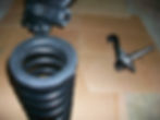

You can tell that I cut down the lower bump stop about 1" and I did decide to install the bumper for the upper control arm. For the record, I cut the lower bumper before installing the spindle and spring. A sawzall made quick work of the problem. With the lower ride height that I am expecting from the Aerostar coils the car is going to need the extra room.


After orienting the studs, I actually install the spindle to the upper arm and get the nut as tight as I can. Then, I pump the jack and bring the lower control arm up to seat the coil in its pocket. On its way up the lower hole in the spindle is filled by the stud in the lower ball joint and with just a few more pumps the stud is all the way through. The top nut is 7/8" and the lower nut is 15/16" socket size. When the stud is all the way through I do like to rap the upper ball joint with a hammer/wood combination to get it to "seat" and take out play (if there is any). That may not be the most ASE certified way to do it, but it gets the job done. I will most probably check those nuts again after the engine is reinstalled and before the car goes to the alignment shop. The large bolts that connect both the upper and lower arms to the frame will be left just tight enough to hold until the full weight of the engine and front end is put back on the suspension and the car is sitting at ride height. Then we will tighten all four down before it moves out to the alignment shop.
I snapped a photo of the differences in front sway bar bushings as well. The old bushing and bracket that was used for the wagon bar was original and was "wallowed" out, dry rotted, and just plain useless as you can see. The new bushings from Energy Suspension are made of polyurethane and are also able to be greased. Once my tube of synthetic grease arrives in the mail I will reinstall the front sway bar, but again only just to keep it on snug until the full weight of the car is down. I did see a big difference between the old bolts and bushings that held the bar to the control arm when I compared the old ones from the wagon bar to the new ones I received. Hopefully it is just a difference in the size/compacting of the rubber grommets.

And finally, a couple shots of the Aerostar Coil Springs before installation. I purchased new rubber insulators and capped them off before putting each one in position. I guess it goes without saying, but you want to make sure you put the flat end up in the frame, and the end with the coil "sticking out" sits in the pocket of your lower control arm. You can follow the guide of the indentation in the tray of the arm to get the correct orientation.
