1955 Ford Part 11: Steering Column, Front End Sheet Metal, Air Ducts, etc
- Hot Rod Reverend
- Sep 21, 2017
- 11 min read
Updated: Apr 3, 2023
(Note: You are reading the progress from a project that began in August of 2014. This information in this post was originally dated from February to May of 2016.)
Steering Column, Front End Sheet Metal, Air Ducts, etc

After much consideration I have decided to completely remove the original 3 speed shifting arm and shaft from the steering column. To maintain some sense of appearance I believe I am going to get a tubular steel shaft that is 5/8" ID and 3/4" OD to mount on the column. The link below is what I plan to use: http://www.onlinemetals.com/merchant.cfm?pid=7765&step=4&showunits=inches&id=283&top_cat=197
I measured the post that is under the cup on the top of the column and it is 5/8" OD. It looks like my plan will work and I can just prime and paint one up to match (I need to touch up the column anyway since I boogered it up a little bit when I put it in the first time.)
I took a photo of the top of the column and the cup. There is a bearing at the top of the tube. At first I thought it was for the steering shaft but the shaft does not even come close to the diameter of the opening. Am I missing a piece or something? I am going to have to check my diagrams and take a look see. The parts are all 56 passenger car pieces, column tube, shaft, steering wheel, etc. One thing I just thought about... I believe there is supposed to be a spring between the bearing up there and steering wheel also.
2 days later....
Got home tonight and what was this?

My order from Online Metals was already here! It is a steel tube 36 inches long, 3/4" OD and little bit less than 5/8" ID.
Ok, so what to do here? I need to get the ID to match up to the stud on the bottom of the steering column cup (5/8" OD exactly). I happen to have a 5/8" drill bit so into the vise goes the steel tube. I wanted to use my drill press but this tube needs to be at least 29" long so I could not find a way to use it. Back to the handheld drill...

I made a mark to let me know how far I needed to go into the steel tube to give me 5/8" ID to slide over the stud.


I watched the drill a good bit during the process to make sure I was getting deep enough, but the label on the tube told the story as the further I went the more burnt the label became - easy breezy! After the ID was widened a little bit the tube was slid over the stud to check fitment.

Next, we went to the lower portion where the shift levers were located and the end cap fits to the steering column tube. At that point we eyeballed the location to give us a cutting reference for length. No need to be so precise here - this is not a service part and will not function. This is solely for aesthetics.

Back to the vise and a cut off wheel and we were in business. The tube fits extremely well and when it is primed, prepped, and painted no one will tell the difference. It will resemble a factory part.
A few weeks later...
The situation with the steering column bearing and bushing was resolved. A few friends on a classic Ford website gave some direction as to what bushing should be used, spring, placement, etc.


The second photo shows the bushing surrounding the shaft and resting in the bearing. This will keep the wobble out of it for sure. For some reason, this was missing in my parts lot I got some time ago when I bought a 56 Ford steering column, shifter, z bar, and manual transmission car parts. I think we have this sewn up now. I did prime and prep the fake shifter shaft that I am going to install to replace the original since we put a Hurst Syncro Loc in the floor. I have only shifted on jackstands, but with the wheels and transmission moving we liked the way she shifted.... smooth. Now to start putting the front end sheet metal back together. But first we needed to assess what we have and take inventory of the clips, hardware, and original rubber seals. I hung the inner fenders and deflectors up in the air and stripped, bagged, and tagged the parts that came off. The air deflectors took a trip to the bead blast cabinet (barely fit in there) and then we set about a plan to work on that nasty driver's side rot.



You can follow along in the photos to see what I did. It is certainly no professional repair, but I liked the results. I need to purchase some sheet metal forming tools - that would help lol.



I also had to weld a tab on the passenger side inner splash pan, just a photo here to double check weld penetration.

Next we were off to paint since the weather was so good. And since we were feeling froggy today and looking for a challenge, I decided to attack the steering wheel with a Dremel tool to open up the gaps - I also took 120 grit sandpaper to it (not shown). I am going to get some PC7 Epoxy and start working on it next week in the basement. I did a 55 wheel for someone out in California about 5 years ago ---- yes, this is work.


(a few weeks later...)
I have been out of town for a few weekends but during some of the weeknights I have been able to get a few things done. I did take steering wheel and fill all of the cracks with epoxy as you can see. The cracks around the base, or inner circle where the spokes meet, were very bad and there was much to fill. I am beginning to see why NOS steering wheels are so pricey. I wonder when a company will start casting OEM Steering Wheels for our cars? I think the tri-5 shebbies have a few companies that offer them.


I am going to let the epoxy cure in the basement tomorrow, so I just hung it from the rafters.... along with the panel that holds down the hood. Would you believe it fit in my blast cabinet? After blasting I brushed it with a new metal prep and primer. I will scuff sand it later after it cures and plan to paint it gloss black.

On to those pesky vent tubes that let in the fresh air or heated air depending on which way you turn the flaps...
The one above is for the passenger side "magicaire" heating system that doubles up the passenger side vent tubes for fresh air, heated air, etc. Both sides actually need new rubber seals. I was planning to blast these pieces and repaint anyway so no big deal. However, drilling out the spot welds can be very tricky when the seal plates are attached the pivot inside the tube.

I guess trying to make things hard on myself, the plan was to drill out all spot welds WHILE THE PLATES WERE STILL IN THE TUBE. How could one accomplish this feat of unneeded skill and expertise? well.... check out the 2x4 cut for the purpose of keeping the plate at a good angle of access. That was all good and well for the passenger side tube. Since access could be gained from 4" hole on the side of the tube, I guess a monkey could have done that with one arm tied behind his back. Ok, so what to do with the other side? I could only drill out a weld or two, and as you can see there were six a SIDE. So, I got the Dremel out and wallowed out the spot welds only on one side of the pivot. This made it easy to push the "opened" side past the pivot and then remove the plate assembly from the tube. I could then put the plates on a vise and drill out the spot welds pretty easily.


I also took the "insulated" sheet metal tubes that are made to connect the 90 degree elbows off the firewall to these tubes and cleaned them up pretty good. Another classic car enthusiast gave some really good advice on using something called Armaflex and then a picture of some material to make a homemade cabin filter for each side.

(the next week...)
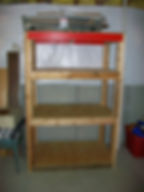
The son and I had a good afternoon together. We did not get too much down on the car or any Y block parts, but we did get to use our brains, hands, and a little math to put together a 2x4 shelving unit in the basement. My garage is just too full of parts, tools, and the like to be able to move around there without my fat rear end knocking something over, getting grease all over me, etc. It is like working in a can of sardines. You guys that have smaller workshops I don't know how you do it!

Anyway, I enjoyed the time with my 13 year old boy, EJ. We just made it from scrap lumber and all as you can see. The measurements are 72" high by 29" deep and 48" wide. She is straight and true on the level. We started putting some boxes and totes on the shelves before I had a chance to grab the camera. She will sit in the basement for a good while - pretty heavy shelving here.
(and....one week later...)
The kits for the vent seal replacement came in while I was out of town...

Whereas the originals were in two pieces (I am pretty sure the originals were installed as a two piece assembly in each tube) the new seals are one piece. Also, there are a good number of machine screws and nuts to put the flappers back together. However, methinks I have one too many holes and will need some more hardware! Ouch.
Here it is May 7th and I feel like I've got nothing done! My air compressor (the heart beat of the shop) went down and I chase the problem for a week or so. It ended up being the start capacitor. No biggie, get it ordered, be here in 4 days, etc. Capacitor shows up - wrong one. Right box, right label, wrong capacitor in the box! Aaarrrrrggghhhh, another 4 days and we have what we need. And... the pressure washer went crazy blowing water everywhere. Seems Karcher uses a lot of molded, high density pvc in their units - this one had a cracked elbow. 5 days and replaced that. My wife drove through some truckers' explosion and she says the smoke and debris made it where she could not see a thing, van covered in all kinds of good, plastic?, black dots, and I don't know what all. 10 hours of a buff job and we are all shiny again - just in time for Mother's Day. I did get those vents squared away. They look good. The seals went into the units without much fanfare, and I put a tick of white lithium grease on the pivots.


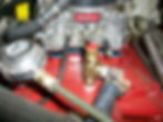
I also got a chance to mount an electric fan and plumbed a thermostatic switch after a visit to Lowe's and the plumbing section. You can see the tee I put in right there behind the thermostat housing on the intake. I could not figure a way to get a good tee and still have good access if I used the original sending unit location on the head at the rear (there is already a sending unit there for the mechanical gauge.)
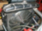
The electric fan went in without too much trouble as well. It is a pretty good unit that I had been using on my portable engine run stand. Would you believe you can get a very good mounting kit on ebay shipped to you for $1? that's right, that's what it cost me - and it looked pretty healthy too and held up that fan nice and tight. And then we have everyone's favorite job - the dreaded steering wheel! I used PC7 epoxy to fill in those cracks and crevices after opening them up and then took a dremel tool to the thing to sand it as level as I dared...ended up using a drum roll. (queue stupid joke ) After I knocked down every bulge I took 120 grit sandpaper to it. Once I got down with the whole hour and a half job (man this is tedious work!) I was a dusty mess! Good thing I used a dual cartridge filter mask. I need to paint the wheel with some primer/surfacer after wiping it down with Acetone. After that I will probably have to fill in some low spots here or there with some glaze. I am not going to spend a whole lot of time on it - it is a driver after all not a show car.


For the last few weeks I have been receiving messages from enthusiasts who have noticed the fuel regulator setup that I have on the 55. Evidently the aftermarket unit I installed is notorious to fail and leak fuel so I did my own research on that Mr. Gasket Fuel Pressure Regulator finally I caved in and purchased another style - it is a 12-1803 unit. New in the box from Holley, it has a mounting bracket, screws to mount the bracket to a firewall or other stable mount, and two "self-tapping" screws to secure the regulator to the bracket.

Not impressed with the hardware - the sheet metals screws had too large a head - they kept hitting the regulator housing. Next thing, the "self-tapping" screws were too long but we did trick that one out quickly. (the fittings and washers in the photo were from my own stash) What I like up front - TWO outlets (for what I am doing here I can put a gauge on one end and of course the line to the carb on the other. When I got to looking at what I was going to do to mount it, I decided to take this route as you can see. Even with the air cleaner on the carb, once I install a gauge it will be easy to read when we pop the hood. Steps taken... Fabricate a support bracket from stock, then attach the regulator bracket to the support bracket (on the level )

Now fit the regulator to the bracket assembly with the fittings already installed from the bench.
Ok now for some plumbing.

I bent up some hard line to go from the regulator to the carburetor. It basically goes underneath of the upper radiator hose (at thermostat housing), takes a dive to the other end and turns back towards the carb just before the passenger side head. Then a couple of roller coaster "dipsy-do's" to get some clearance and then up to the carburetor. I did put a filter just after the pump as well. All I had on hand was a cheapie - will have to get another one before this old 55 is put on the road permanently. I do like the clearance now though and this is a much better routing back to the carburetor. We also have more room for the connection made at the thermostatic switch for the cooling fan. Oh and I am still sanding and working on this guy too!
(a couple weeks later...)

Got back from being out of town and just had to get in the garage for some therapy. I decided to remove all of the trim (save the rear bumper and the windshield/glass trim) so I could begin the body work and paint process. First up, the doors. The passenger door is the "worst" of the two but won't require much. I am going to treat some of the rust on the inside cavity and then paint inside, making sure that the drain holes are good.
Next, a wonderful find... the previous owner decided to hold each of the Fairlane Crowns on the doors with this goo Must be pretty good stuff. After 25 years or so they never fell off!
All of the upper window openings have rust like this:

That will be fun. Of course we had a slew of clips and fasteners to deal with but I had to ask myself a question from this photo:

Which one is original? I assume the one on top that is "square" right? The other one (like some of the other clips) simply broke off in my hand when I gave a gentle tug on the SS trim pieces. And then how about this? Check out the paint - serious crow's feet pattern going on. This paint job is about 25 years old but the white is in serious trouble like this all the way around the car. The red is in excellent shape and looks like it could have been painted 3 years ago. What gives?

I went ahead and took 120 grit sandpaper to a patch of the white paint on the rear quarter panel just to see, then I took it to 400. I cleaned it with thinner and this is what it looked like still, although you could not physically feel any crow's feet you can still see them. After some further research I decided that eventually all of the white would have to be completely stripped to bare metal.
