1955 Ford Part 19: Hood, Trunk, Custom A/C, and Heater Hose Guard
- Hot Rod Reverend
- Sep 30, 2017
- 12 min read
Updated: Dec 27, 2019
(Note: You are reading the progress from a project that began in August of 2014. This information in this post was originally dated from March to May of 2017.)
Hood, Trunk, Custom A/C, and Heater Hose Guard
The hood was primed, and what will probably be the final two coats of primer surfacer were shot onto the trunk. It gets better with each session. I had to hang the hood in an interesting way on my panel cart so that I could paint both sides in one session.


When I checked the mail today, what was this in the mailbox?

Now what can this be?
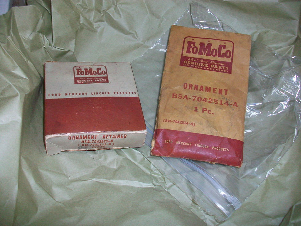
Oh yes, an NOS find! A beautiful hood crown bezel with plastic insert... very nice - check it out.

After looking at those pictures it seems like the color is off, but I assure you it is not. I guess the flash on the camera changes the color hue at different angles. (a week later...)
Why I get involved in little projects like the one I am about to explain, I don't know. Maybe it is the satisfaction of fabricating something small that will be entirely functional and serve a purpose, maybe it's the OCD part of me that just can't let things rest, who knows? Take tonight's overkill for instance. Not wanting to have the heater hoses touch the alternator as they run back from both the intake manifold and the water pump caused me to come up with a simple way to make a bracket from pieces of scrap I had lying around. 1/8" flat stock and some 18 gauge sheet scrap and way we go! First up was to trim the flat stock:

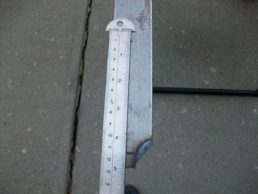

I drilled a 15/32" hole with the press, planning to make a slot that the bolt that tightens the alternator could use to keep the bracket in place. I also found a stainless bowl about the circumference of the alternator to give me the arc I wanted. (I measured this a few times to see what angle/distance on the arc I liked best off the alternator - crazy how much changing the attachment point of the upright to the sheet metal changed the angle of attack for the heater hose bracket I was fabbing up.) Next was to get a good rectangular shape out of that sheet metal piece that would essentially be rail for the hoses to ride on. About 6.5 by 4 or so...

Then we judiciously fitted the sheet metal to the arc at the top of the upright (1/8" flat stock) and got them both cleaned up and ready for welding by using a magnet to give us a 90 degree angle.(the straight edge was used to check our distance on either side of the bracket, we didn't want to weld anything up without the two pieces being as square as we could get them.) A couple of tacks and then on the backside...
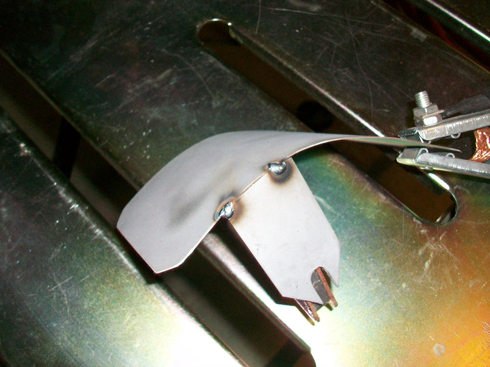


We checked our welds and we had good penetration. I decided not to go too crazy since this was sheet metal and very easy to blow through. After cleaning up the welds the brand new part went into the blast cabinet...
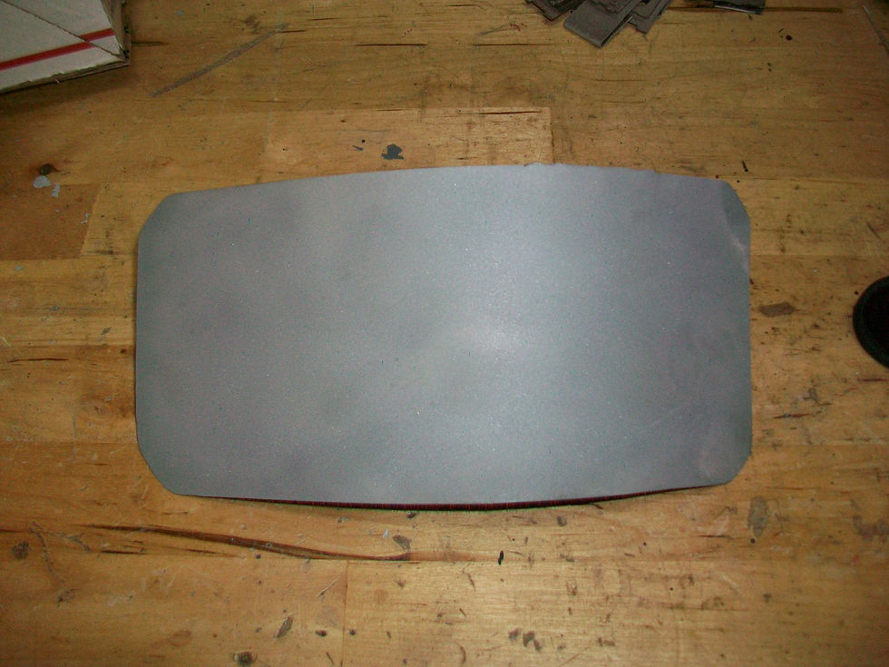
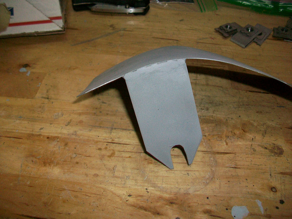
What welds? lol Not quite perfect but good enough for what we are doing here. And here is the fitment before painting the bracket –
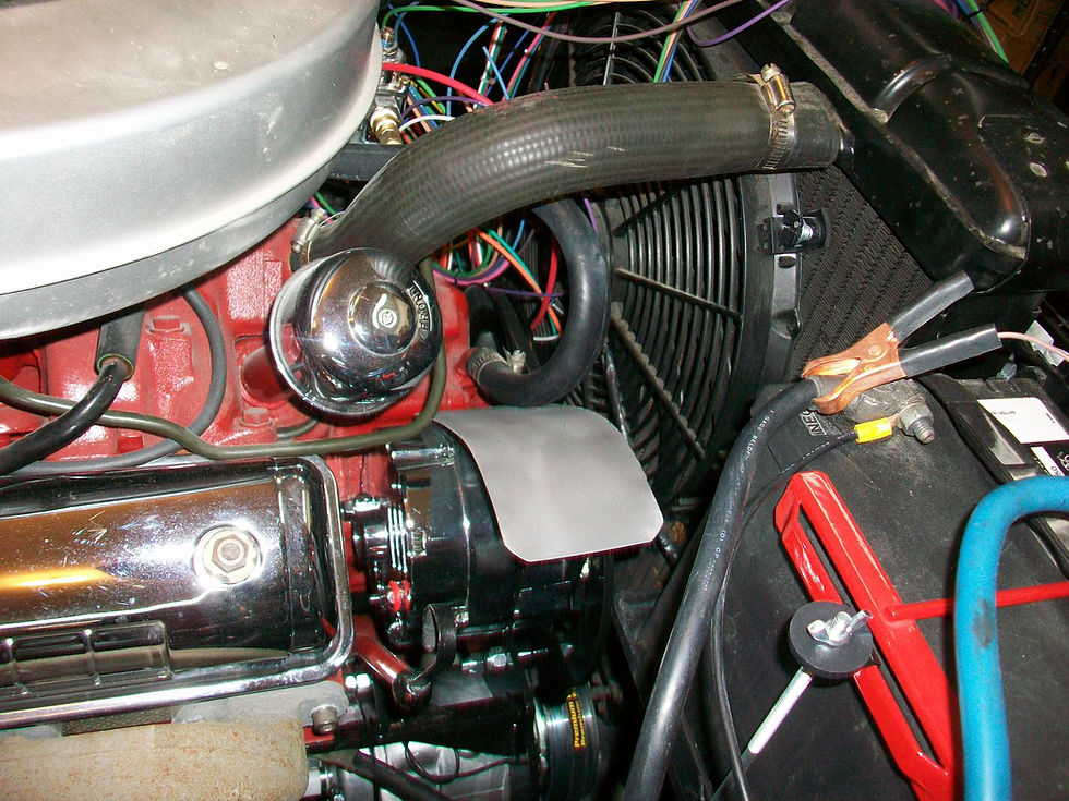

If you know the way that the stock heater hoses run, they take this exact path as they head to the inner fender on the passenger side just aft of the battery. There is a special FoMoCo bracket that keeps the hoses resting on the fender - I can only assume that this is to keep them from flopping around. I have more photos of the trunk and the hood but it is pretty boring stuff, just block sanding, more block sanding, and a little more block sanding! Although, the trunk is about ready for color! Got a little more done today - we will take some time to talk about a product I really like so far: TAMCO HC 2100 Clear Coat. Times have changed since the early 90s when I worked at a shop out in Manassas Park, Virginia. The helpful advice on a number of classic car restoration sites has been invaluable. With all the online assistance I have been given, it would be easy to consider myself an expert. When plans are put into practice, that is really where the difference between a novice and expert show up. I am still on the novice side. My pieces don't look like professional panels but that's ok - I am satisfied with my build and getting oo's and ah's from the fellas that take a look at the work when they come by the house - they can tell I have put some quality time and effort into it. The car is going to be a daily driver and not a show car, but when I get ready to build a 60s Mustang for the wife on our 25th anniversary I will be light years ahead of the game. One such expert advice I have received has to do with the clear coat I mentioned. A while back I was introduced to possibility of using clear coat by one of the old men at our church who is a retired body man, having worked in the industry for over 40 years and built over 10 cars of his own. He recommended I go that route. On another site I learned about a Euro clear labeled HC 2100. Now remember when I say all of this I am a novice - if you look up the definition of the word there is a picture of me standing there grinning ear to ear with a paint gun in my hand lol. There are probably other clears that are better than this product at $130 a gallon. Today I shot three coats of this clear on the exterior of the trunk lid. While the pictures at this point cannot do it justice, when the Tamco HC 2100 clear says it is "self-leveling" it ain't kidding.

Take this first example...

Yes, that is a bug, and yes, that is picture of the two toothpicks I used as a set of tweezers to pull said bug from my freshly clearcoated trunk!


It is difficult to see in the second photo but when that bug was removed the clear coat "leveled" out. 5 minutes later and I could not tell where the bug had been. Add to that my small mistake of having a one inch run during my 3rd coat (yes, I waited 30 minutes for the previous coat to flash, just got too close on my pass). I don't know if anyone would believe it unless I had a video but THAT RUN LEVELED OUT TOO. Needless to say I am very happy with this clear - it almost seems like it was made for guys like me that are not that experienced, do not have a professional paint booth, and need a little "magic" from their products to get the job done. Just want to say again I am very grateful for the advice from you fellas out there who contribute your autobody knowledge. As we know, much of the work that goes into restoration includes body and paint!
Look what came in today! The AC kit I ordered some time ago has plenty of fittings/etc for a standard install, but this install is not going to be "standard".
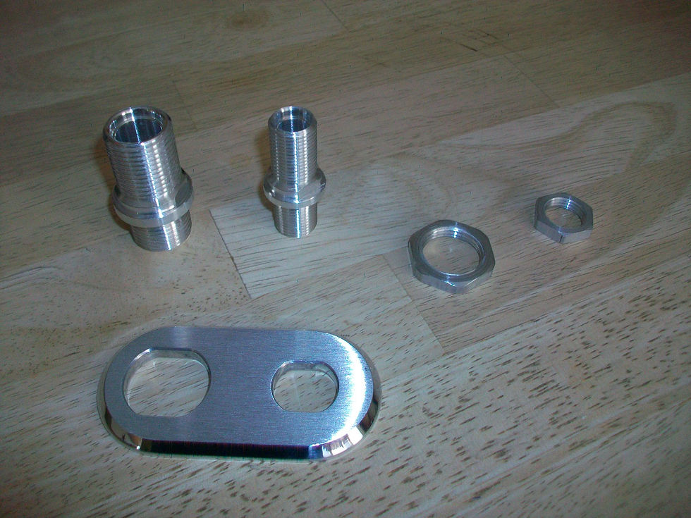
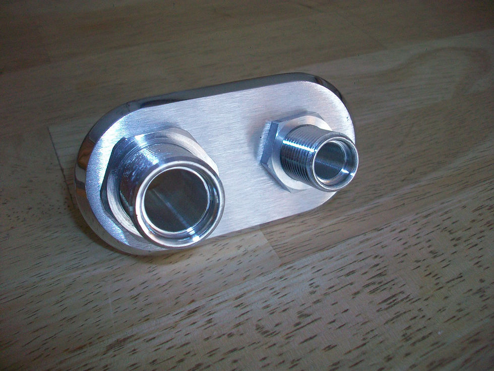
I wanted a clean pass through the firewall, hence the bulkhead fitting. Also, since I am using a Vintage Air bracket that puts the compressor extremely low. I am going to use inline service ports for the HI and LO sides. I also ordered a small plethora (is that even a phrase?) of various fittings and sizes so that I won't be locked in to the fittings from the original kit (with the bulkhead I needed fittings anyway). I like where the condenser, drier, compressor, and evaporator are all sitting. It will now be a matter of plumbing all of this up while using the original heater parts and controls.


I did plunk down some change for the Mastercool crimper. I did some research and read reviews - they all seemed to be pretty good on this unit. I will certainly let you know what we discover. When I found out how much places wanted to crimp hoses I just decided it would be good to get my own crimper. I have to make quite a few for this AC install, and of course Mama keeps talking about a late 60s Mustang she wants to have done for her 25th wedding anniversary. That car will have to have an AC unit as well. And.....that car will have to wait as well - gotta get this one done first. Anyone have a lead on a late 60's Mustang? :) I will be out of town again this weekend but hopefully I can get to some of this stuff. I did make myself a little diagram so that I can follow along as to how I am installing this system. Once I get the fittings chosen and the lengths of hose all dialed in I will add that to the diagram as well.
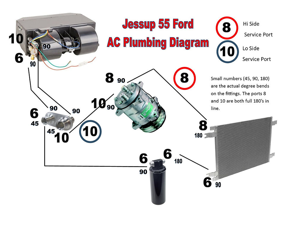
(edit: the diagram above is current as of the summer of 2017)
And some outdoor shots on this trunk... I got home tonight and decided to get it out, go over it with 2000 and then run the buffer real quick - still want to do one more pass but my wife came by at the end and just dropped her jaw and stood and looked at the trunk and then looked at me.

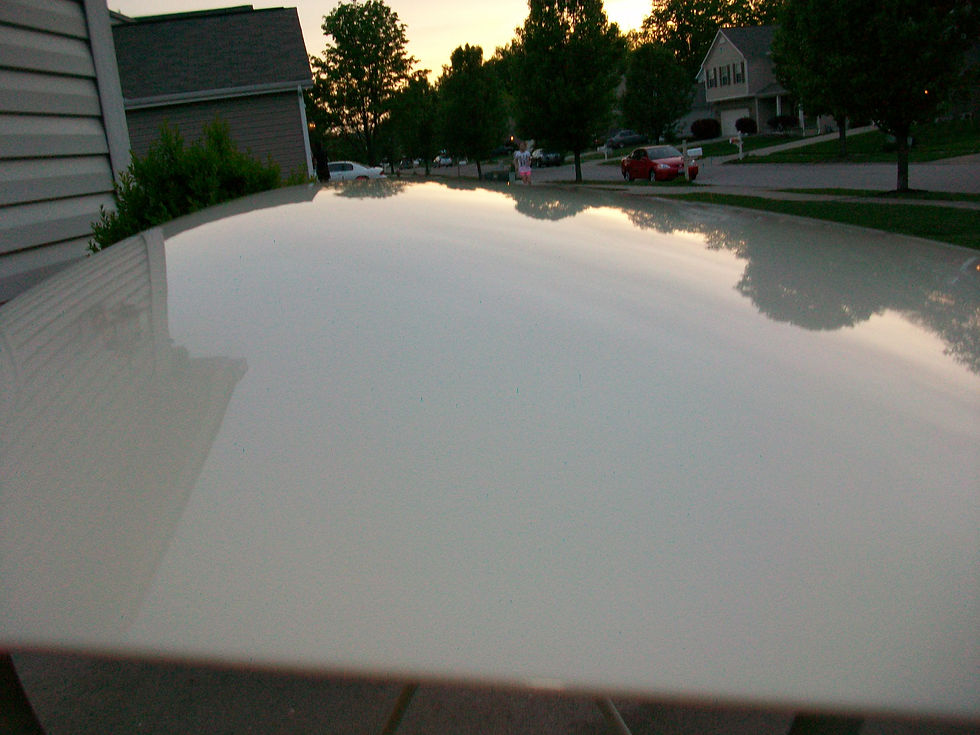

I just nodded lol! Hopefully I can continue this trend through the build. I do think much of this is due to the quality of the clear coat I am using - it's awesome stuff. Take away the amateur portion of this work and the products used would really stand out. If you have been following this blog that seems to be 15 miles long, you know that I decided to plunk down some coin and purchase a crimping tool that would help me get the AC lines and fittings together. I figured it was a good idea since the wife wants me to start putting together a Mustang for her in a few years. The tool is from a company called "Mastercool" and seems to be very well made. It is designed to be placed in a vise as you crimp your lines. The main unit is heavy, and the tool comes with 4 different sizes of crimping inserts, 6, 8, 10, and 12. (did not need the 12 for this installation) The tool I purchased also came with a nice plastic, blow-molded case to keep the entire unit and inserts together.

Basically the idea here is that you set your fitting in the crimper, insert your hose to the end of the fitting (each one has a sight hole so that you can be sure you have inserted far enough) and then use a wrench or ratchet to cinch the ends together - the inserts crimp the fitting and hose together.
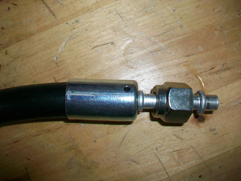

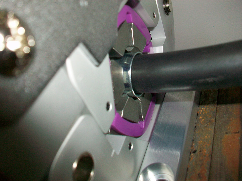
I made sure the fitting and hose were centered in the bore before I hand tightened the press, and then after doublechecking I used a 3/4" wrench to bring it all together. There is a mark located on the boss so that you know how far to go...

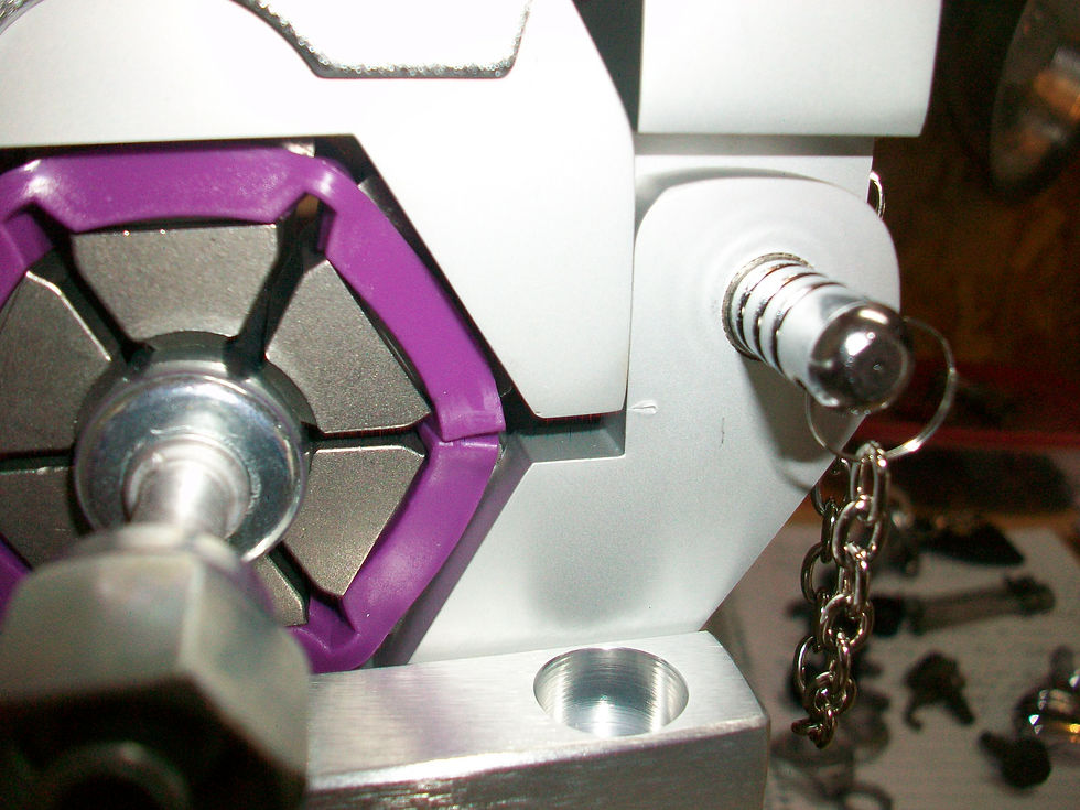
The tool works as advertised and the crimps look to be even and of course that hose is very tight in the fittings! For some hoses you make you will end up with fittings that need to be oriented to a particular "clock" or angle. Of course, if one end is a straight 180 degree fitting then there is no issue. I marked my fittings and hoses by using a sharpie and making sure the fitting and hose were oriented correctly before I cinched them down.

Of course, keep a little mineral oil on hand for those O-rings, and make sure you don't cut them as they go on the fittings/get connected to fittings in the car.

I am pretty happy with the AC kit I purchased - although the price point seemed to make it a "budget kit" the hoses shipped with the kit are obviously name brand "Parker" - a well recognized name in the industry.


Thought I would post some pictures of what I did to route the lines and how I situated the bulkhead fitting where the lines pass through the firewall. At this point I am not finished with the plumbing since I want to get my heater sheet metal installed first and I am not 100% sure how I want to route in the engine bay itself, I am HAPPY that I bought a number of various fittings ahead of time. This is definitely a custom install and different bends/sizes are needed all over the place - especially with that bulkhead fitting. First up, the receiver/drier line... used one 180 and one 90 to put this together. This install was pretty straight forward. The size 6 line goes behind the horn on the passenger side.


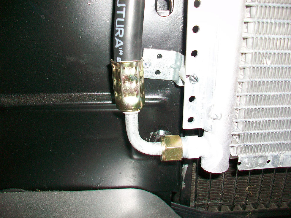
Next up was to determine where the bulkhead fitting was going to go. I decided the best place would be on the same plane with the evaporator and the fortunate thing for me was that this placed the pass through point directly below the heater duct that attaches to the firewall. If you are thinking, "Great, he is burying the fitting where he cannot reach it later on..." Just remember that the sheet metal plenum at the firewall is easily removed with the two levers on the heater core boss and the clamp that attaches the square duct.
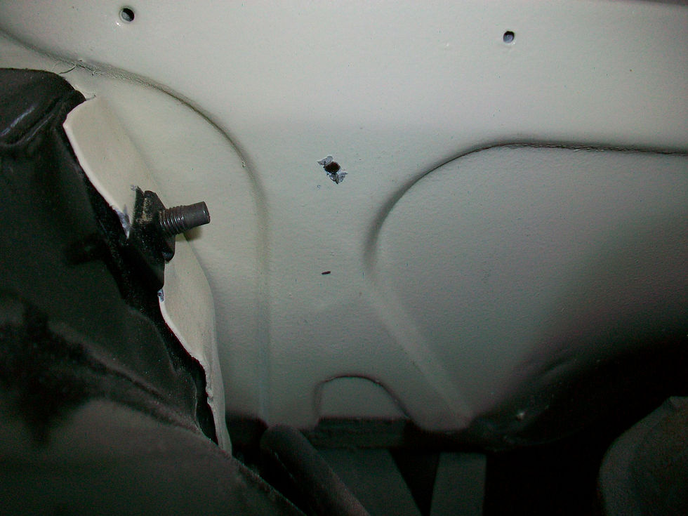


I placed the fitting plate on the engine side of the firewall and made a mark, then used a punch to give me a locating point. Next up was a step drill to give me the first hole (size 6 fitting). Then I attached the plate/fitting to give me a reference point for the larger hole on the bottom - this one needed a 1 1/4" hole saw.

after a little clean up...
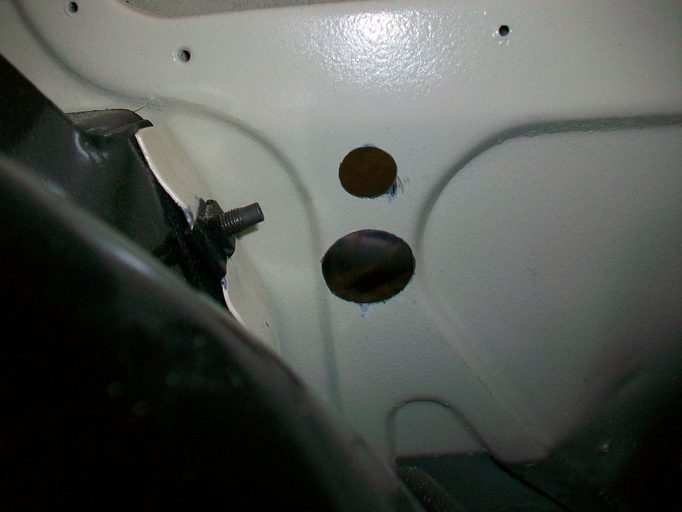
Once I checked the fitment of the bulkhead fitting I used some 3M weatherstrip sealant on the back of the plate so we wouldn't get any leaks later on.
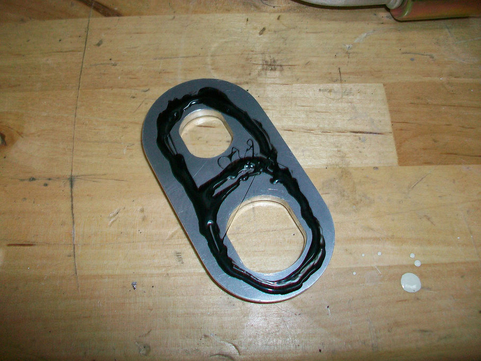
and we attached the two fittings, plate, and the nut and voila!

Back to the inside of the car now. I played around with various fittings - 90 degree, 45 degree, and 180 degree - to find out which orientation would work best.
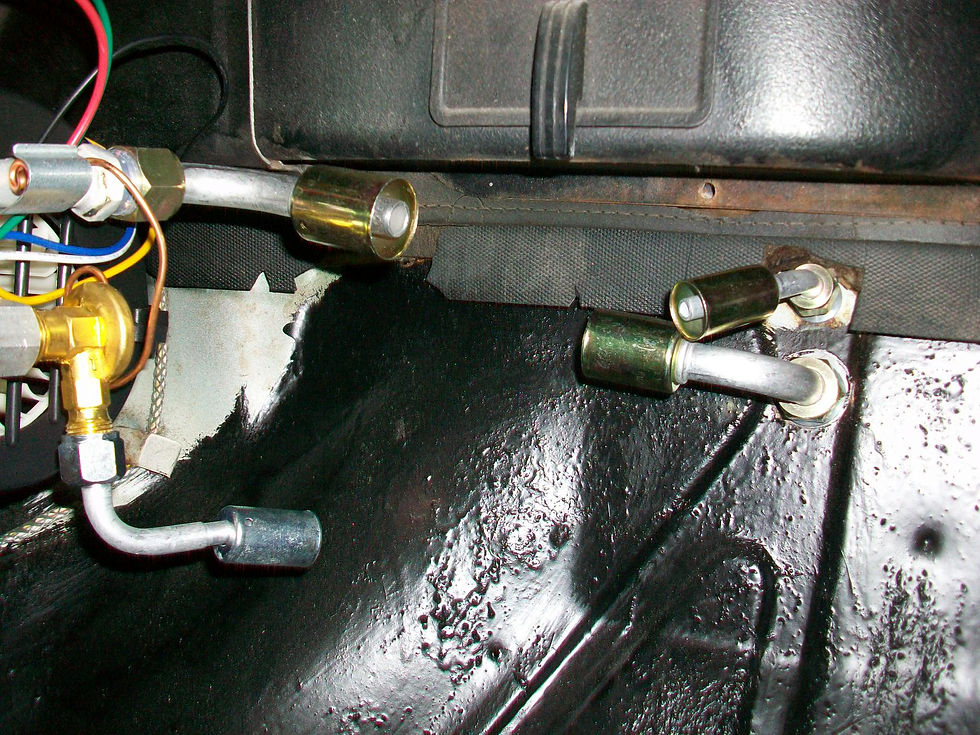
If you are paying attention you can see that the lines will criss-cross as they pass through the firewall. This is "by design" - this time I actually thought about this ahead of time since I knew where we were headed with the size 6 line and the size 10 line moving up front. I also had to orient the fitting in "portrait" and not "landscape" on the firewall so this configuration worked best. It really was not a big deal. However, if you look at the photo above you will see that the size 10 fittings are just not lining up. I did have to work them a little with some judicious, altered, bends so that they would line up to each other. Since I was not dealing with any 180's on this evaporator hook up, the first fitting was crimped to the hose after a general measurement was taken. Then that fitting and the hose was installed. I then took the other fitting that the hose was connecting to and installed that with the hose in the final fitting "uncrimped". This made the jockeying around very easy and I just marked the fitting to the hose, pulled everything out, crimped, and reinstalled. I am not sure if that is the way it is supposed to be done but it worked for me and I am happy with the way it all went together. I am also very PLEASED I bought this Mastercool crimper. I could not imagine the multiple trips to a shop to have the ends crimped without being able to tell what I was doing. Some guys may be good enough to handle that but I am not.


Next up was the size 6 hose for the evaporator and by this time it was getting to be standard operating procedure, and then get the lines from the bulkhead to the compressor, condenser, and receiver/drier up front. If I can get as much installed as possible it should be easier to figure out where the ports need to go. With a rear exit compressor and the Vintage Air bracket that puts the compressor almost out of reach, I am planning to bring both the Hi and Lo ports over between the starter solenoid and the heater box somewhere.

(a few weeks later...)
Between projects such as pressure washing the deck, repairing a water hose, hanging a window for the wife, painting hardware for the wife, and other Saturday busyness I did have a chance to get a few things done. I installed the heater core and box since my new gaskets arrived yesterday. Even though they are Made in the USA, they leave much to be desired and are not the same thickness as the FoMoCo versions.


Take these photos for instance. Notice the gap in each one as it gets a little tighter each time I adjust the levers on the Heater Core boss.

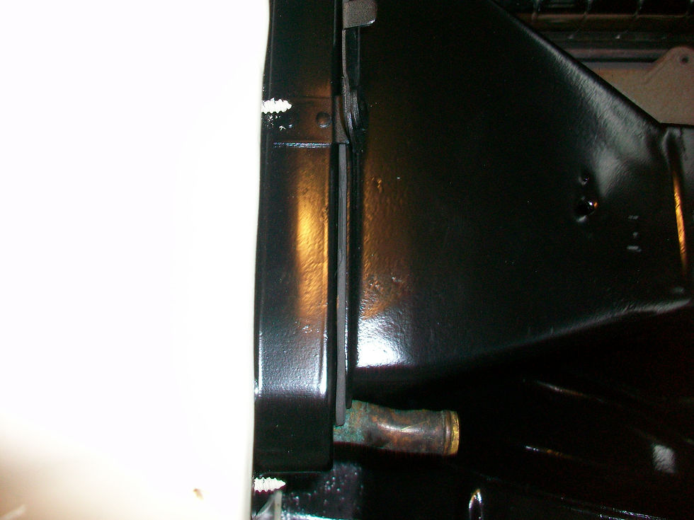
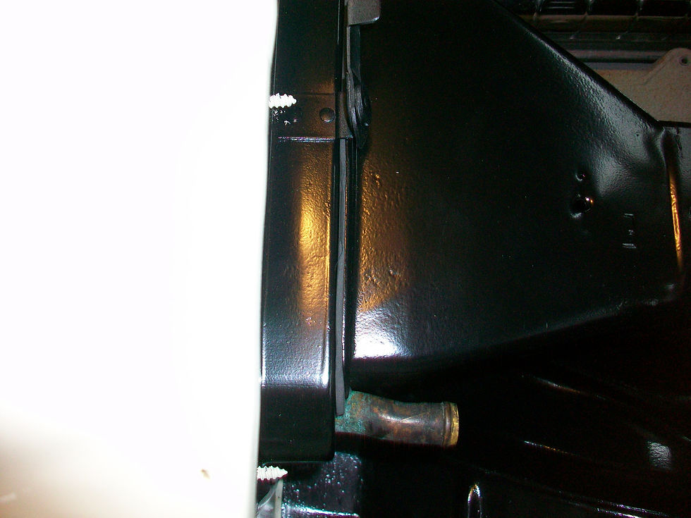

We are sealed up but I don't think these are going to last near as long as Ford's original equipment. I decided to work on the Heater parts because the AC lines I am running are weaving in and around the units and I wanted to get an idea of where to put the Hi and Lo ports for access. I settled on the Lo port (which is a size 10 hose in this setup) to be just forward of where the squirrel cage boss sits. This should be pretty easy to access but it will be tucked out of the way.

When the special AC grommets I ordered arrive, I will take some photos of how I plan to orient and install the final line from the compressor to the condenser (we will also show the ports at the rear of the compressor - it is tight in there!)

Comments